
Quản gia năng lượng của bạn
Short circuit error of PV cathode to ground in photovoltaic system and solutions.
Đăng ngày | No Comments
Analysis of the dangerous principle of the problem
Currently, non-isolated inverters that are applied in the TN power grid system (N ground wire system), cannot operate under grounded PV conditions. If the device operates the PV part, a problem will occur, and will damage the inverter device.
Figure 1 is the circuit diagram of a two-level inverter (take the single-phase diagram as an example), and figure 2 is the corresponding negative (-) phase ground fault diagram. As can be seen in Figure 2, if the grid switches K1 and K2 of the inverter are closed, when the grid load is half a cycle, a large current will flow through the switch tube Q2, although at This inverter detects hardware overcurrent and commands K1 and K2 to turn off, but because the relay’s response time is in milliseconds, the induced current is enough to damage the diode body of Q2 before completely cutting off. , thus causing damage to the inverter. 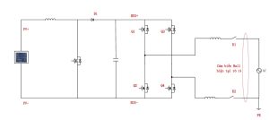 Figure 1: Two-level Inverter circuit diagram (single-phase diagram).
 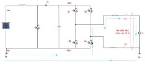 Figure 2: Circuit diagram of negative phase (-) ground fault circuit of two-level inverter (single-phase diagram).
Solution 1
Check the insulation resistance before starting the machine. You must check the insulation resistance of the PV to ground. If the check shows abnormal insulation resistance, the inverter will need to be started in the neutral state. load, i.e. K1 and K2 must be disconnected, and no current will flow through Q2. Thus, inverter protection is achieved. However, during the inverter’s operation, the (-) PV phase has a problem. Due to the relay response time problem, the inverter is still at risk of being damaged.
Solution 2
Add a fuse for the (-) PV phase During operation, if a PV (-) short circuit to ground occurs, when the grid load is half a cycle, there will be a large current flowing through the switch. switch of Q2 and fuse F2, at this time the fuse will break first, and interrupt the current, to protect the machine. The fault diagram is presented in Figure 3.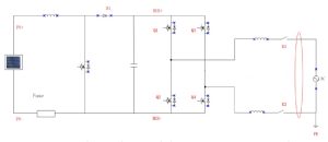 Figure 3: Circuit diagram of negative phase (-) ground fault of a two-cable inverter (negative phase (-) with fuse attached).
Solution 3
Do not ground wire N of the low voltage side of the grid-connected transformer. Many 3-phase power stations connected to the distribution grid do not connect directly to the 380 V power source, but through a 400 VAC / 10 kV transformer. fight in. In this case, the N wire on the low voltage side must not be grounded, to avoid the transformer during operation, when a PV negative short circuit error during operation will damage the inverter.
Bài viết mới nhất


37 Bùi Hữu Nghĩa, Phường An Hải Bắc, Quận Sơn trà, Thành phố Đà Nẵng
+84 846 39 19 68
contact@solareye.vn
Leave a Reply